Logic Design for Array-Based Circuits
by Donnamaie E. White
Copyright © 1996, 2001, 2002, 2008, 2016 Donnamaie E. White , WhitePubs Enterprises, Inc.
- Table of Contents
- Preface
- Overview
- Chapter 1 Introduction
- Chapter 2 Structured
Design Methodology
- Chapter 3 Sizing the
Design
- Functional Specification - A Closer Look
- Review the Available Arrays
- Architectual Specification or Hardware Specification
- Array Sizing
- Cell Capabilities
- Array Architecture
- Netlist
- Example: AMCC Interface Options
- Example - AMCC Arrays - Power Supply Options
- Interface Cell Functionality
- Examples
- Internal Cell Functionality
- Multi-Cell Macros
- Hard and soft macros
- Refining Interface Requirements
- Adding Extra Power and Ground Macros
- Dual-Function I/O Macros
- Example - Simultaneously Switching Outputs
- Thermal Diodes
- The AMCC Speed Monitor
- Final Interface Cell Utilization
- Drivers
- Exercises
- Chapter 3 Appendix = Case Study in Sizing a Design
- Chapter 4 Design Optimization
- Chapter 5 Timing Analysis for Arrays
- Chapter 6 External Set-up and Hold Times
- Chapter 7 Power Considerations
- Case Study: DC Power Computation
- Case Study: AC Power Computation
- Chapter 8 Simulation
- Case Study: Simulationest
- Chapter 9 Faults and Fault Detectiond Output
- Chapter 10 Design Submission
- ASIC Glossary
Sizing the Design - Selecting the Array
Array architecture
The base arrays for the various series are similar in their design concept in that the core of most arrays is composed of an array or matrix of logic or basic cells organized in a row-column configuration. Arrays that contain memory place the RAM blocks in the core area, with the rest of the core designated for internal logic cells. Phase-Lock loop arrays, the PLL arrays, have PLL locations that straddle both core and interface areas. Interface (I/O) cells are placed around the perimeter of the array interspersed with power and ground.
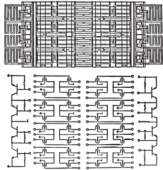
There are different base arrays for different power supply configurations. The base array for a single +5V supply will be different from that for a mixed-mode +5V/-5.2V dual supply. A generic die plot for the Q20080 array is shown in Figure 3-1 and one for the BiCMOS Q24091 is shown in Figure 3-2, with the interconnect pattern in Figure 3-3.
Figure 3-1 Q20080 Die Plot
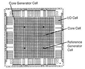
Figure 3-2 Q24140 Die Plot
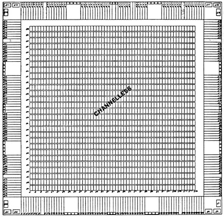
Figure 3-3 BiCMOS Macro Interconnect Pattern
Macro Configurations
Macros are individually configured by interconnecting the components within a cell with one layer of metal to form the selected macro function. Macros can occupy a cell, a partial cell (usually 0.5 cell), or require several cells. The internal interconnect for a simple macro is generally confined to one layer of metal. The particular layer will depend on the array series.
Cell Interconnect
The process of interconnecting macros is called routing. For channelled architec tures, routing is performed following specific routing tracks. The interconnect is on the first and second layers of metal in a two layer metalization array. Horizontal and vertical tracks are assigned to specific metal layers.
For an array with three layers of metal, the second and third layers will be used for inter-macro routing and the first layer for intra-macro routing. In practice, the hard definition of which layer of metalization is restricted to which operation can be blurred.
Channelless Architecture
Channelless architectures have been developed to avoid some of the limitations im posed by restricted number of routing tracks.
The Q24000 sea-of-gates and Q20000 sea-of-cells (channelless) architectures use three layers of metal. Macros are interconnected on one level and interconnect between macros occurs on the other two, the specific layers being array and series dependent.
For the Q20000 Series arrays, the internal macro connects (intraconnects) are on second and third metal with macro and I/O interconnects on the first layer. Routing on all three layers is possible and four layers of metal is a future possibility.
Todays arrays have 6 or 8 leyers of metalization, and the base die has grown from 3 to 12 inches in diameter.
Copyright © 1996, 2001, 2002, 2008, 2016 Donnamaie E. White , WhitePubs
Enterprises, Inc.
For problems or questions on these pages, contact [email protected]