Logic Design for Array-Based Circuits
by Donnamaie E. White
Copyright © 1996, 2001, 2002, 2008, 2016 Donnamaie E. White , WhitePubs Enterprises, Inc.
- Table of Contents
- Preface
- Overview
- Chapter 1 Introduction
- Chapter 2 Structured
Design Methodology
- Chapter 3 Sizing the
Design
- Functional Specification - A Closer Look
- Review the Available Arrays
- Architectual Specification or Hardware Specification
- Array Sizing
- Cell Capabilities
- Array Architecture
- Netlist
- Example: AMCC Interface Options
- Example - AMCC Arrays - Power Supply Options
- Interface Cell Functionality
- Examples
- Internal Cell Functionality
- Multi-Cell Macros
- Hard and soft macros
- Refining Interface Requirements
- Adding Extra Power and Ground Macros
- Dual-Function I/O Macros
- Example - Simultaneously Switching Outputs
- Thermal Diodes
- The AMCC Speed Monitor
- Final Interface Cell Utilization
- Drivers
- Exercises
- Chapter 3 Appendix = Case Study in Sizing a Design
- Chapter 4 Design Optimization
- Chapter 5 Timing Analysis for Arrays
- Chapter 6 External Set-up and Hold Times
- Chapter 7 Power Considerations
- Case Study: DC Power Computation
- Case Study: AC Power Computation
- Chapter 8 Simulation
- Case Study: Simulationest
- Chapter 9 Faults and Fault Detectiond Output
- Chapter 10 Design Submission
- ASIC Glossary
Sizing the Design - Selecting the Array
Dual-Function I/O Macros
The AMCC library offered complex macros for space density.
Each added power and ground macro uses a pad and disables the cell that is associated with that pad, reducing the number of these cells and pads available for I/O operations. To offset this waste, many macro libraries include dual-function macros that use the I/O cell for one function and the pad for added ground. Two to three I/O cell positions might be used by these complex macros.
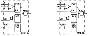
Refer to UE54 below. There are two pads used, but the logic for the 3-input NAND agte and inverting output requires the "guts' of two I/O cells. By pairing this complex macro with a pad-only ECLVCC, we have no wasted logic space and efficient use of silicon.
One macro, OT35, contains a 3-state driver (internal logic) and an added TTL GND. It sits on an I/O cell. IE33D was a differential input buffer, with an ECL VCC. Takes up three PADs. OE15 is a 3-input OR/NOR internal logic gate producing differential outputs (50 Ohm termination) with an ECLVCC. Also three PADS. Refer to the macro description files.
Silicon efficiency can be achieved with the dual function macros. The macros available are array series-specific and vary widely. If any of these functions applies to the design, they can reduce silicon requirements while maintaining functionality. (See Figure 3-7.)
Example macros include:
- input function with 3-state enable driver
- 3-state enable driver with added ground
bidirectional input with added ground
Figure 3-7 Example Dual-Function I/O Macro (UE54/UK54)
Example - Simultaneously Switching Outputs
All AMCC arrays, with the exception of the Q20000 Bipolar Series and the BiCMOS Q24008 array, use the following rules for adding power and ground due to simultaneously switching outputs (SSO), called an output group.
Allow 8 TTL SSO outputs per quadrant, then add one TTLPWR and one TTLGND macro for each group of 1-8 after the first eight. This requires two cells, two pads and, depending on the package, two package pins. Add another pair for the next group of 1-8 and another for the next group of 1-8 and so on. All TTL output counts are converted to "equivalent" 8 mA outputs. (See Table 3-16.)
For packages with internal power and ground planes, place the TTLPWR and TTLGND macros so that they are interspersed with the simultaneously switching outputs and can be bonded to the power or ground package plane.
Table 3-16 Sample Rules for Adding TTL Power and Ground
| PER TTL SSO | ADD TTLPWR, TTLGND PAIRS: |
|---|---|
| 0-8 | do nothing |
| 9-16 | add 1 pair |
| 7-24 | add 2 pairs |
| Etc. |
Allow 8 ECL SSO outputs per quadrant, then add one ECLVCC macro for each group of 1-8 after the first eight. This requires one cell, one pad and, depending on the package, one package pin. Add another pair for the next group of 1-8 and another pair for the next group and so on.
For packages with internal power and ground planes, place the ECLVCC macro so that it is interspersed with the simultaneously switching outputs and can be bonded to the power or ground package plane as required. Note: ECLVCC is a power pad in a +5V reference ECL circuit (5V REF ECL) and a ground pad in a standard reference ECL circuit. (See Table 3-17.)
Table 3-17 Sample Rules for Adding ECL Power OR Ground
| PER ECL SSO | ADD ECLVCC | Q20000 Rules |
|---|---|---|
| 0-4 | do nothing | do nothing |
| 4-8 | do nothing | add 1 |
| 9-12 | add 1 | add 2 |
| 13-16 | add 1 | add 3 |
| 17-21 | add 2 | add 4 |
| 21-24 | add 2 | add 5 |
| Etc. | Etc. |
The Q20000 Series requires one ECLVCC per additional 1-4 ECL SSO after
the first group of four. All output counts are converted to "equivalent"
50 ohm outputs. The extremely high speeds of these arrays require design
procedures to ensure minimal noise.
Copyright © 1996, 2001, 2002, 2008, 2016 Donnamaie E. White , WhitePubs
Enterprises, Inc.
For problems or questions on these pages, contact [email protected]