Logic Design for Array-Based Circuits
by Donnamaie E. White
Copyright © 1996, 2001, 2002, 2008, 2016 Donnamaie E. White, WhitePubs Enterprises, Inc.
- Table of Contents
- Preface
- Overview
- Chapter 1 Introduction
- Chapter 2 Structured Design Methodology
- Chapter 3 Sizing the Design
- Chapter 3 Appendix = Case Study in Sizing a Design
- Chapter 4 Design Optimization
- Chapter 5 Timing Analysis for Arrays
- Chapter 6 External Set-up and Hold Times
- Case Study: Preventing Hold Violations Due To Clock Skew
- Computing Hold Time in the Register Example
- Minimum Library (Q5000 Series)
- Military Library (Q5000 Series)
- Exercises
- Chapter 7 Power Considerations
- Case Study: DC Power Computation
- Case Study: AC Power Computation
- Chapter 8 Simulation
- Case Study: Simulation
- Chapter 9 Faults and Fault Detection
- Chapter 10 Design Submission
- ASIC Glossary
External Set-Up and Hold Times
Last Edit July 22, 2001
Case Study: Preventing Hold Violations Due To Clock Skew
Hold Time Considerations
Assume a typical 32-Bit shift register being driven by two clocks. No extraordinary design considerations are needed to maintain hold time when the Q output and D input are on flip/flops that are driven by the same clock net. (See Figure 6-4.) The AMCC Q5000 Bipolar macro library is used in the example.
Figure 6-4 32-Bit Register: Single Clock Path
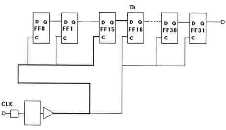
If the clock nets are different (Figure 6-5), the two clock paths need to be analyzed to determine if the required hold time has been satisfied. Differences in tracking, fan-out and metal lengths between the paths can be significant and cause enough delay in the second path (PATH 2) to create a hold time
Figure 6-5 32-Bit Register: Two Clock Paths, Balanced Tree
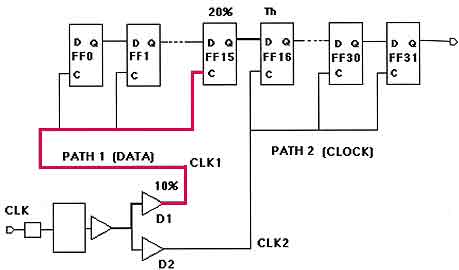
CLK through D1 and through clock->Q on FF15 is the data path for the hold time computation for FF16. CLK through D2 and coming into the C input of FF16 is the corresponding clock path. The macro hold time, shown as Th for FF16, cannot be violated.
Copyright © 1996, 2001, 2002, 2008, 2016 Donnamaie E. White , WhitePubs
Enterprises, Inc.
For problems or questions on these pages, contact [email protected]