Logic Design for Array-Based Circuits
by Donnamaie E. White
Copyright © 1996, 2001, 2002, 2008, 2016 Donnamaie E. White, WhitePubs Enterprises, Inc.
- Table of Contents
- Preface
- Overview
- Chapter 1 Introduction
- Chapter 2 Structured Design Methodology
- Chapter 3 Sizing the Design
- Chapter 3 Appendix = Case Study in Sizing a Design
- Chapter 4 Design Optimization
- Chapter 5 Timing Analysis for Arrays
- Chapter 6 External Set-up and Hold Times
- Case Study: Preventing Hold Violations Due To Clock Skew
- Computing Hold Time in the Register Example
- Minimum Library (Q5000 Series)
- Military Library (Q5000 Series)
- Exercises
- Chapter 7 Power Considerations
- Case Study: DC Power Computation
- Case Study: AC Power Computation
- Chapter 8 Simulation
- Case Study: Simulation
- Chapter 9 Faults and Fault Detection
- Chapter 10 Design Submission
- ASIC Glossary
External Set-Up and Hold Times
Last Edit July 22, 2001
Computing Hold Time in the Register Example
To compute the hold time of the design, the propagation delay of both paths needs to be determined while factoring in the effects of tracking.
- The worst-case tracking occurs when tracking
- reduces the path propagation delay of both the
- clock path PATH1 and the clock-to-output (Tpd)
- delay of the last flip/flop in the chain that is
- connected to PATH1 (FF15). This includes both
- the intrinsic and extrinsic delays.
The general equation for the example is as follows (using 10% tracking for the first macro in PATH1, and 20% tracking for the second macro):
| 10% | 20% | |
| WCM * | [ 0.9 * Tpd D1 + | 0.8 * Tpd FF15 - Tpd D2 ] > Th FF16 |
| TRK1 | TRK2 |
where Tpd is nominal. For the example, the driver macros (D1) are identical and placed within the same chip quadrant. For the Q5000 Series, this has been specified to mean a 10% tracking (0.9). For identical macros on the same row in the same quadrant, this reduces to 5% tracking or 0.95. TRK1 will be taken at 10%.
The second tracking factor (TRK2) applies to FF15. This accounts for unlike edges and unlike structures between D2 and FF15. It does assume that both are placed within the same quadrant.
For macros that are not identical, placed in the same quadrant on the array, tracking is defined as 20% or 0.8. TRK2 will be taken as 20%. These numbers only apply to the AMCC Q5000 Series. The timing diagram for Figure 6-5 is shown in Figure 6-7.
Minimum Library (Q5000 Series)
For the example, for a military circuit, using bipolar worst-case multipliers (AMCC Q5000 Series), the equation for the Minimum Library minimum values becomes:
0.86 * [0.9 * Tpd D1 + 0.8 * Tpd FF15 - Tpd D2] > Th FF16
The Minimum Library is specified with worst-case multipliers of 0.86 (MAX), 0.78 (TYP) and 0.70 (MIN).
Figure 6-7 Timing Diagrams
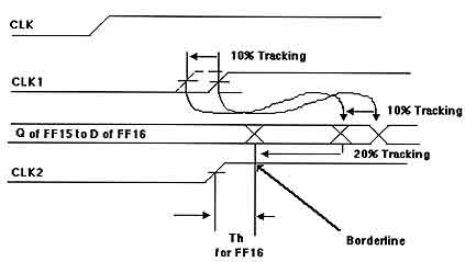
In Figure 6-7, FF15 Tpd C->Q (clock to output delay) may be 20% faster than nominal. The total effect of these two variations may be to cause the D input to FF16 to change within the hold time window.
Military Library (Q5000 Series)
The equation for the Military Library maximum value becomes:
1.45 * [0.9 * Tpd D1 + 0.8 * Tpd FF15 - Tpd D2] > Th FF16
The Military Library is specified with worst-case multipliers of 1.45 (MAX), 1.32 (TYP) and 1.19 (MIN).
The computation should be performed using the MAXIMUM (Military or Commercial, as appropriate) worst-case library and then using the MINIMUM library to determine the worst-case external hold time. The ratio of the data and clock path delays will determine which library will produce the larger (most positive number) hold time.
While success can be estimated using Front-Annotation, final calculations must be made after Back-Annotation using the actual metal delays. The layout and/or design must be changed if the appropriate test fails.
Note that tracking may be part of the adjustment factor specifications, in which case the equations would need to be altered to reflect this different specification. Check with the array vendor.
Exercises
- Review the design manual for the array you have chosen.
-
a. How is tracking specified?
b. How are external set-up and hold-time specified?
c. What guidelines are given to minimize the hold-time problems in circuits such as shown in Figure 6-3? - . Compare the array chosen in exercise one with a second array (different series, different vendor).
- Write the generic equations for external set-up and hold time for the case where the propagation delays are specified as nominal and the macro set-up and hold times are specified as worst-case.
- . Change the register case study to the macros in a library of interest.
Write the hold time tracking analysis equations for this circuit. You
need to know:
- how macros are specified - Tpd;
- how macros are specified - Tsu, Th;
- if worst-case multipliers or adjustment factors are to be used,
- what they are; for like and unlike edges,
- how the vendor specifies tracking;
- and how macro extrinsic loads (net and fan-out loads) are computed.
Copyright © 1996, 2001, 2002, 2008, 2016 Donnamaie E. White , WhitePubs
Enterprises, Inc.
For problems or questions on these pages, contact [email protected]