Logic Design for Array-Based Circuits
by Donnamaie E. White
Copyright © 1996, 2001, 2002, 2008, 2016 Donnamaie E. White, WhitePubs Enterprises, Inc.
- Table of Contents
- Preface
- Overview
- Chapter 1 Introduction
- Chapter 2 Structured Design Methodology
- Chapter 3 Sizing the Design
- Chapter 3 Appendix = Case Study in Sizing a Design
- Chapter 4 Design Optimization
- Chapter 5 Timing Analysis for Arrays
- Chapter 6 External Set-up and Hold Times
- Case Study: Preventing Hold Violations Due To Clock Skew
- Computing Hold Time in the Register Example
- Minimum Library (Q5000 Series)
- Military Library (Q5000 Series)
- Exercises
- Chapter 7 Power Considerations
- Case Study: DC Power Computation
- Case Study: AC Power Computation
- Chapter 8 Simulation
- Case Study: Simulation
- Chapter 9 Faults and Fault Detection
- Chapter 10 Design Submission
- ASIC Glossary
External Set-Up and Hold Times
Last Edit July 22, 2001
Overcoming Hold Time Error
Two options are available to overcome the problem of hold time error.
- Add one or more gates in PATH1 to offset the delay that has been found in PATH2. Generally, a single gate will suffice (B1, a buffer). (See Figure 6-6)
- Minimize the differences to an acceptable level through macro selection,
placement, load balancing and reduced metal lengths.
- Use identical clock driver macros to improve tracking. In buffer trees, use identical macros within the trees.
- Balance the clock fan-out loading (Lfo) to within 10%. In a buffer tree, divide the loads to be as evenly distributed as possible, within 1 or 2 loads of each other.
- Balance the clock load delays (fan-out + metal)
(k fo * L fo + k net * L net)
to within 30%. This requires placement considerations and possible preferential placement.
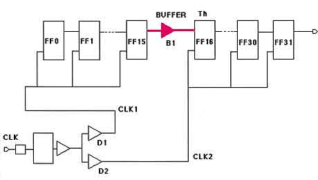
- Add a buffer if computation still shows a hold time violation (data changing too fast for clock). This is B1 in Figure 6-6 (between FF15 and FF16 because that is where the clocks switch from sourced by PATH1 to sources by PATH2).
Figure 6-6 32-Bit Register: Two Clock Paths, Balanced Tree, Buffer Added
Design Check
To compute the hold time of the design, the propagation delay of both paths needs to be determined while factoring in the effects of tracking. For the Q5000 Series, the effects are defined below.
For Like edges
- If like edges and like structures where they are placed on adjacent cells on the same row or column, a 5% tracking is specified for AMCC Q5000 and Q14000 arrays. The amount will vary with the array and with the manner used by the vendor to specify tracking.
- If the two drivers are of the same macro type and they are placed within the same quadrant, a tracking of 10% is specified for the AMCC Q5000 and Q14000 arrays. Check with the vendor for the array to be used.
- If they are not the same macro but are placed within the same quadrant, 20% tracking is specified for the AMCC Q5000 and Q14000 arrays.
Check with the vendor for the array to be used.
The buffer B1 in Figure 6-6 adds delay to the data path to prevent the hold time violation for th of macro FF16.
For unlike edges
- If unlike edges and unlike structures but placed within the same
quadrant, 20% tracking is specified for the AMCC Q5000 and Q14000 arrays.
Check with the vendor for the array to be used. The variations will
usually be between 20 and 50%.
Other placement options are not recommended.
Note: It is unlikely that two paths whose tracking in relation to each other is of concern, would be placed in different quadrants. If they are, consult with the array vendor.
Copyright © 1996, 2001, 2002, 2008, 2016 Donnamaie E. White , WhitePubs
Enterprises, Inc.
For problems or questions on these pages, contact [email protected]