Logic Design for Array-Based Circuits
by Donnamaie E. White
Copyright © 1996, 2001, 2002, 2008, 2016 Donnamaie E. White , WhitePubs Enterprises, Inc.
- Table of Contents
- Preface
- Overview
- Chapter 1 Introduction
- Chapter 2 Structured Design Methodology
- Chapter 3 Sizing the Design
- Chapter 3 Appendix = Case Study in Sizing a Design
- Chapter 4 Design Optimization
- Chapter 5 Timing Analysis for Arrays
- Chapter 6 External Set-up and Hold Times
- Chapter 7 Power Considerations
- Case Study: DC Power Computation
- Case Study: AC Power Computation
- Chapter 8 Simulation
- Case Study: Simulation
- Chapter 9 Faults and
Fault Detection
- Introduction
- Controllability
- Observability
- Masking a Fault
- Fault Types
- Fault Equivalencies
- Single Stuck-At Faults
- Minimal Test Sets
- Example Test Set
- The Problem
- Combinatorial Circuit
- Formation Rules for the Existence Function
- Forming Links
- Selecting a Chain
- Advantages of the Test Sequence
- Simple Gates - Sequences
- Extension to Three-State and Bidirectional Structures
- Extension to Sequential Circuits
- Reference
- Case Study - 16:1 MUX D Flip/Flop Circuit
- Chapter 10 Design Submission
- ASIC Glossary
Faults and Fault Detection
Last Edit July 22, 2001
Single Stuck-At Faults
The most common fault for current technology is the single, permanent, stuck-at fault where one of the actions shown in Table 9-3 has occurred.
Table 9-3 Stuck-At Faults
- A gate output is stuck at logical 0
- A gate output is stuck at logical 1
- Any single gate input is stuck at 0
- Any single gate input is stuck at 1
The single fault assumption is not valid during design debug and prototype circuit checkout. Design errors are interpreted as faults during the design debug process. Process errors and mask errors produce faults during the prototype analysis phase. The single fault stuck-at test vectors can be used to assist the debug process, although it may be overkill to debug with vectors that are formatted under rigid tester requirement rules.
Component failures that alter or affect voltage levels, current levels, pulse widths or circuit timing, but which do not alter or affect the logical function realized by the circuit will not be detected by stuck-at testing.
Other testing is required to characterize the array.
Table 9-4 Miscellaneous Testing
- Voltage threshold levels, VIH and VIL, are tested during parametric testing.
- Device timing characterization is detected by either an AC speed monitor or AC tests.
- Thermal measurements of the array are made using thermal diodes.
Minimal Test Sets
There are dozens of procedures that have been developed to allow the creation of minimal test sets, those sets of input vectors that all 100% fault coverage of all detectable fault locations in a circuit. Masked faults are not detectable.
To be complete, a test set must be able to detect any single detectable fault, any multiple faults that are not single fault equivalent, and those faults that can be uncovered when another undetectable fault occurs (a special type of multiple fault).
Example test set
The simple 2-state logic AND-OR circuit implementing Y = X0X1 + X2X3 has seven nets, including the four inputs and one output. There are fourteen unique single fault locations. Faults at the beginning and the end of a net are considered equivalent faults. There are 84 possible double fault combinations. All 84 double faults are covered by the fourteen single faults. All faults will be detected by the vector set which tests for the fourteen single stuck-at faults. (See Figure 9-2.)
Other testing is required to characterize the array.
Figure 9.2 Example Circuit
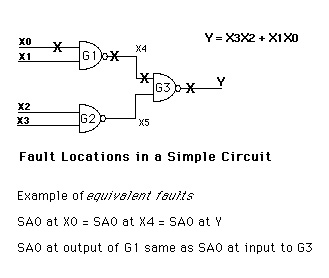
As a further reduction, not all fourteen single faults are distinct. As an example, a test for X0 SA0 (stuck-at-0) also tests X4 SA0 and internal net X6 SA0. This means that the final minimal test set is something less than 2**4 = 16 tests.
Copyright © 1996, 2001, 2002, 2008, 2016 Donnamaie E. White , WhitePubs
Enterprises, Inc.
For problems or questions on these pages, contact [email protected]