Bit-Slice Design: Controllers and ALUs
by Donnamaie E. White
Copyright © 1996, 2001, 2002, 2008 Donnamaie E. White
- Pre-Introduction
- Selection of the Implementation
- Microprogramming
- Advantages of LSI
- The 2900 Family
- Language Interrelationships
- Controller Design
- Constructing the CCU
- Sequential Execution
- Multiple Sequences
- Start Addresses
- Mapping PROM
- Unconditional Branch
- Conditional Branch
- Timing Considerations
- Pipelining
- Improved Architecture
3. Adding Programming Support to the Controller
- Expanded Testing
- Subroutines
- Nested Subroutines
- Stack Size
- Loops
- Am29811
- Am2909/11
- CASE Statement (Am29803A)
- Microprogram Memory
- Status Polling
- Interrupt Servicing
- Implementation - Interrupt Request Signals
- Vector Mapping PROM
- Next Address Control
- Am2910
- Am2910 Instructions
- JZ, CONT, JMAP
- CJP, CJV, LDCT, JRP, CJS
- JSRP, CRTN, RPCT, PUSH
- LOOP, CJPP, TWB
- Control Lines
- Interrupt Handling
- Am2914
- Interconnection of the Am2914
6. The ALU and Basic Arithmetic
- Further Enhancements
- Instruction Fields
- Instruction Set Extensions
- Sample Operations
- Arithmetic -- General
- Multiplication with the Am2901
- Am2903 Multiply
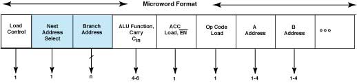
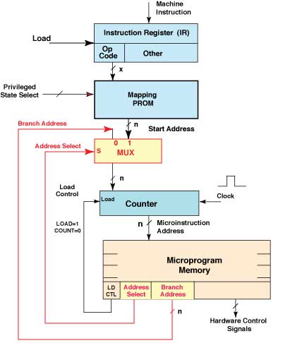
Simple Controller continuedLast Edit October 10, 1996; May 1, 1999; July 9, 2001 Unconditional BranchOften microroutines may start differently but end with the same steps. Also, once starting addresses are mapped (and the microinstruction position in memory fixed), it might be found that a microroutine needs to be extended in length. For these and other cases, the existence of a GO TO or unconditional branch next-address control is desirable. The instruction flow is shown in Figure 2-8. This instruction causes the counter to be loaded with the desired next address, which is not in sequence with the current address. This is not a start address; therefore, the map is not involved. Instead, the microword width must be expanded as shown in Figure 2-9 to contain a branch address field, up to n bits wide, and a next-address-select field. The map and the branch address lines would be input to a 2:1 MUX network, n bits wide, with the MUX select operated by the address selection field of the microword. The MUX outputs are the inputs to the counter, as shown in Figure 2-10. Figure 2-8 Flow Diagram of Unconditional Jump - the GOTO statement (JMP, jump)
Figure 2-9 Expanded Microword.
Figure 2-10 CCU With Branch Capability
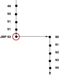
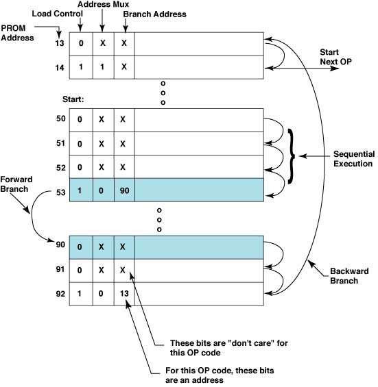
A sample piece of microcode, shown in Figure 2-11, highlights the load control to the counter, the address MUX select, and the branch address field. Assume that the program start address is at address 50. Execution is then seen to be sequential until address 53, which loads the counter (LDCTL=1) with a branch address (ADR MUX=0) supplied at address 53 (BR ADR=90). The next microinstruction executed is located at address 90. Address 90 causes a branch back to address 13. Address 14 causes the counter to be loaded (LDCTL=1) with a new start address (ADR MUX=1). This is the last step in the microroutine that began at address 50. Figure 2-11 Microcode, Demonstrating the Use of Jumps. (X bits are "don't care" for this op code; numbered bits are address for this op code.)
The width of the branch address field, B, could be less than n, restricting the allowable range of the branch (for example, by leaving the n - B high-order bits unchanged). This complicates the task for the microprogrammer and should be avoided by beginning designers. Good programming practices require that the various parts of the microroutines be kept in a relatively compact area, if possible, without artificial enforcement. |