Refining the CCU
Last Edit November 2, 1996; May 1, 1999; July 7, 2001
Interconnection of the Am2914
Single Unit
The Am2914 requires that the status overflow pin be connected to
the interrupt disable pin. The GAR and GEN pins are grounded; GAS,
GSIG, RDIS, and PDIS are left floating. When the highest priority
interrupt is reached, the interrupt controller is disabled until
a new status is loaded or a master clear is executed. The highest
level interrupt should be reserved for catastrophic occurrences.
For all other status levels, when a higher status is to be executed,
and recovery is desired, the existing status should be read so that
it may be reloaded upon completion of the higher level interrupt,
if another higher level interrupt has not occurred in the interim.
Care should be taken to eliminate or reduce cycles in status read
and load operations. (Possibly a decrementing of the current status
and check on interrupts is a better unwinding procedure.)
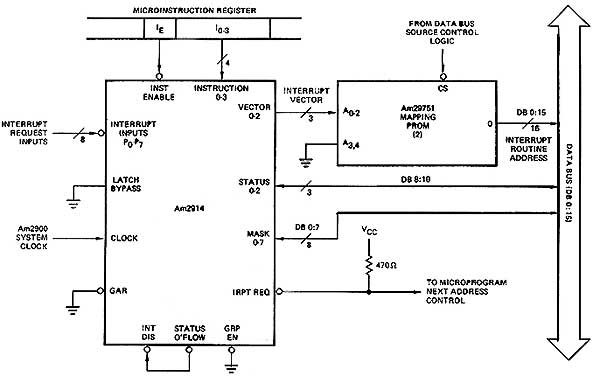
Interconnection
To interconnet a single Am2914 to the microsystem, the Am2914 must
receive four instruction bits and an instruction enable bit from
the pipeline register. The 16-bit system data bus would be used
to supply the 3-bit status read/load lines and the 8-bit mask read/load
lines. The vector output would feed the vector mapping PROM or other
decode unit, which in turn would connect to the 16-bit data bus.
The eight interrupt request lines would be connected to whatever
interrupts are to be allowed in the proper priority sequence. The
interrupt request line is tied high through 470ohms and inputs to
either the CC' input of the Am2910 or some similar connection. This
provides an 8-level interrupt control system (see Figure 4-31).
Figure 4-31 An 8-level interrupt control unit
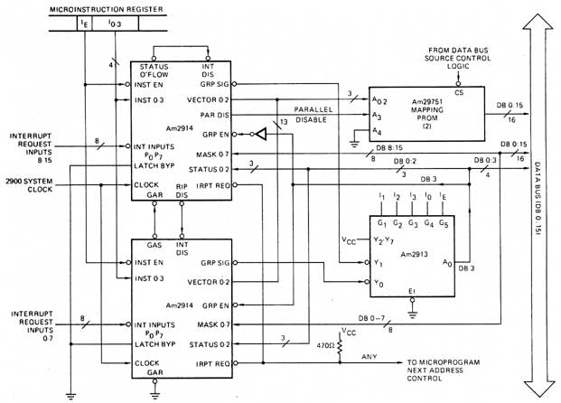
A 16-level interconnect is shown in Figure 4-32 using an
Am2913 expander; 64-level systems are demonstrated in an AMD application
note.
Figure 4-32 16-level interrupt control unit for Am2900 system
Microprogram Interrupt
The Am2914 interrupt controller may be interconnect to provide
a microprogram level interrupt system or a machine program interrupt
system.
In the former, the microcode would contain tests for the occurrence
of any interrupt at "quiet" points in the microcode. There are placed
where the subroutine stack is empty, such as at the end of the microroutine
for an opcode or between modules within a very long microroutine.
The response to the interrupt is relatively fast; the op code itself
is unchanged, but it does require additional control memory storage.
The occurrence of an interrupt would cause a branch address to
be input to the PROM/ROM (through the Am2910 ro Am2911s), which
in turn would cause the interrupt service microroutine to begin
executing. The end of this service microroutine would cause either
a return to the interrupted op code miroroutine or a JMAP to fetch
the next op code.
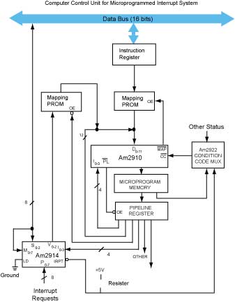
The interrupt routine could be called by a simple conditional jump
or by a sonditional jump to subroutine. A controller using an Am2910,
and an Am2914 is shown in Figure 4-33
Figure 4-33 Computer control unit for microprogram interrupt
system
Machine Level Interrupt
A machine program interrupt system may test for an interrupt only
at the end of the microroutine for the current opcode since
the contents of the instruction register will be destroyed. The
existence of an interrupt in this case would cause the vector map
to output to the system data bus.
Two procedures could exist. In the first, the vector map output
could in fact be a special opcode. The microroutine for this special
opcode would exist in the PROM memory, and a start address would
exist for the microroutine in the memory map. This is a relatively
fast procedure but requires space for the opcodes and a large control
memory.
In the second, the vector map output would be processed by system
software and would be used to call up a machine level interrupt
program. The program would be executed as any other software program.
This is a relatively slow interrupt service procedure, with the
advantages of having no additional microprogram PROM requirements
and requiring no additional map space.
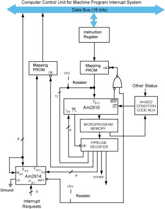
A computer control unit for machine program interrupt handling
si shown in Figure 4-34, constructed from an Am2910 and two
Am2914s. Note that this version does not require a decoder for the
output enable of the memory map. As shown, the OE'vect
must come from the microword just as the instruction register load
control and other system controls do.
Figure 4-34 Computer control unit for machine program interrupt
system
|